Toyota Camry (XV70): Installation
INSTALLATION
PROCEDURE
1. INSTALL REAR ENGINE OIL SEAL
(a) Using height adjustment attachments and plate lift attachments, place the engine assembly on a flat level surface.
NOTICE:
- Using height adjustment attachments and plate lift attachments, keep the engine assembly level.
- To prevent the No. 2 oil pan sub-assembly from deforming, do not place any attachments under the No. 2 oil pan sub-assembly of the engine assembly.
- Using an engine sling device and engine lift, secure the engine assembly before servicing.
| (b) Apply MP grease to the lip of a new rear engine oil seal. NOTICE:
|
|
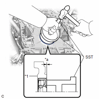
(c) Using SST and a hammer, tap in the rear engine oil seal.
SST: 09223-15030
SST: 09950-70010
09951-07150
Oil Seal Protrusion Height:
-0.5 to 0.5 mm (-0.0197 to 0.0197 in.)
NOTICE:
Do not tap in the rear engine oil seal at an angle.
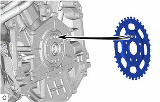
2. INSTALL NO. 1 CRANKSHAFT POSITION SENSOR PLATE
| (a) Install the No. 1 crankshaft position sensor plate. HINT: Align the pin of the No. 1 crankshaft position sensor plate with the pin hole of the crankshaft. |
|
3. INSTALL DRIVE PLATE AND RING GEAR SUB-ASSEMBLY
| (a) Using SST, hold the crankshaft pulley. SST: 09213-70011 09213-70020 SST: 09330-00021 |
|
.png)
(b) Clean the 8 bolts and 8 bolt holes.
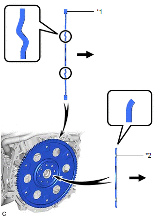
(c) Install the drive plate and ring gear sub-assembly and rear drive plate spacer to the crankshaft.
|
*1 | Drive Plate and Ring Gear Sub-assembly |
|
*2 | Rear Drive Plate Spacer |
.png) |
Transaxle Side |
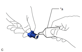
| (d) Apply adhesive to 2 or 3 threads at the end of each of the 8 bolts. Adhesive: Toyota Genuine Adhesive 1324, Three Bond 1324 or equivalent |
|
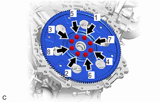
| (e) Install and uniformly tighten the 8 bolts in several steps in the sequence shown in the illustration. Torque: 83 N·m {846 kgf·cm, 61 ft·lbf} NOTICE: Do not start the engine for at least 1 hour after installing the drive plate and ring gear sub-assembly. |
|
4. INSTALL AUTOMATIC TRANSAXLE ASSEMBLY
Click here
.gif)
READ NEXT:
 Fuel Filter
ComponentsCOMPONENTS ILLUSTRATION
*1 FUEL PUMP
*2 FUEL SUCTION PLATE SUB-ASSEMBLY
*3 FUEL SENDER GAUGE ASSEMBLY
*4 FUEL FILTER
*5 FUEL MAIN VALVE ASSEMB
SEE MORE:
Yaw Rate Sensor Wrong Installation (X0456)
DESCRIPTION The airbag sensor assembly has a built-in yaw rate and acceleration sensor and detects the vehicle condition.
Code Tester Display
Measurement Item Trouble Area
X0456 Yaw Rate Sensor Wrong Installation
History of yaw rate sensor (airbag sensor assembly) bein
Doors
Unlocking and locking the doors from the outside
◆ Smart key system (if equipped)
Carry the electronic key to enable this function.
Grip the driver's door handle
to unlock the door. Holding
the driver's door handle for
approximately 2 seconds
unlocks all the doors. Grip
the front p
