Toyota Camry (XV70): Removal
REMOVAL
CAUTION / NOTICE / HINT
The necessary procedures (adjustment, calibration, initialization or registration) that must be performed after parts are removed and installed, or replaced battery removal/installation are shown below.
Necessary Procedures After Parts Removed/Installed/Replaced|
Replaced Part or Performed Procedure |
Necessary Procedure | Effect/Inoperative Function when Necessary Procedure not Performed |
Link |
|---|---|---|---|
|
Battery terminal is disconnected/reconnected |
Perform steering sensor zero point calibration |
Lane Tracing Assist System |
|
|
Pre-collision System | |||
|
Memorize steering angle neutral point |
Parking assist monitor system |
| |
|
Panoramic view monitor system |
|
PROCEDURE
1. PRECAUTION
NOTICE:
- After turning the engine switch off, waiting time may be required before disconnecting the cable from the negative (-) battery terminal. Therefore, make sure to read the disconnecting the cable from the negative (-) battery terminal notices before proceeding with work.
Click here
.gif)
- When replacing the battery, use a new battery of the same dimensions with a capacity of 70 Ah or more at a 20-hour rate.
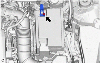
2. DISCONNECT CABLE FROM NEGATIVE BATTERY TERMINAL
| (a) Loosen the nut, and disconnect the cable from the negative (-) battery terminal. NOTICE: When disconnecting the cable, some systems need to be initialized after the cable is reconnected. Click here |
|
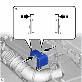
3. REMOVE BATTERY
(a) Disengage the 2 claws and remove the battery terminal cap from the positive (+) battery terminal in the order shown in the illustration.
|
*a | Side View of Claws |
 |
Push Battery Terminal Cap Here |
 |
Push |
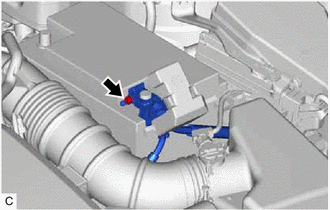
| (b) Loosen the nut and disconnect the cable from the positive (+) battery terminal. |
|
| (c) Remove the bolt and No. 2 battery clamp from the battery clamp sub-assembly. |
|

(d) Remove the battery from the vehicle.
READ NEXT:
 Installation
INSTALLATION PROCEDURE 1. INSTALL BATTERY
(a) Install the battery to the vehicle.
(b) Install the No. 2 battery clamp to the battery clamp sub-assembly with the bolt.
Torque: 18.5 N
2gr-fks Coolant
ComponentsCOMPONENTS ILLUSTRATION
*1 RADIATOR CAP SUB-ASSEMBLY
*2 RADIATOR DRAIN COCK PLUG
*3 NO. 1 ENGINE UNDER COVER
- - ReplacementREPLACEMENT CAUTION / NOT
2gr-fks Drive Belt
ComponentsCOMPONENTS ILLUSTRATION
*1 FRONT FENDER APRON SEAL RH
*2 V-RIBBED BELT RemovalREMOVAL PROCEDURE
1. REMOVE FRONT WHEEL RH Click here
2. REMOVE FRONT FENDER APRON
SEE MORE:
Body
BODY TIGHTEN BOLTS AND NUTS ON CHASSIS AND BODY
(a) If necessary, tighten the bolts and nuts on the chassis parts listed below.
Front axle and suspension
Drivetrain
Rear axle and suspension
Brake system
Engine mounts
Other chassis parts
(b) If necessary, tighten the bo
Diagnosis System
DIAGNOSIS SYSTEM DESCRIPTION The main body ECU (multiplex network body ECU) and certification ECU (smart key ECU assembly) control the LIN communication system. LIN communication system data and Diagnostic Trouble Codes (DTCs) can be read through the Data Link Connector 3 (DLC3).
When the system s
